
Skip to content
The Encyclopedia of Horology

Clock · Electric slave clock mechanism

Electric time piece

Partially verified

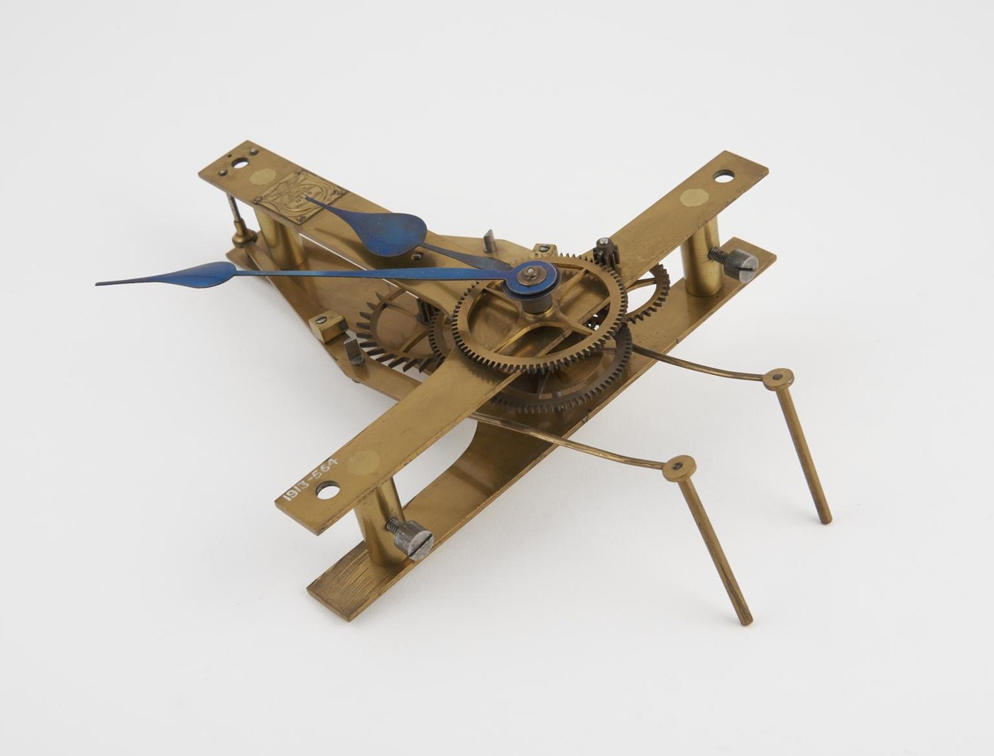
This electric time piece, documented by its 1872 British patent, functions as an electrically-maintained slave clock mechanism. Lacking a traditional dial or pendulum, the device comprises an open brass framework supporting the motion work for the clock hands and a reversed escapement system. It is designed to interface with pendulums that are maintained by electrical currents transmitted every second from a master clock. The mechanical operation relies on two gravity arms, which are lifted by the motion of the pendulum; when these arms fall, they drive the escape wheel. The assembly includes a set of blue-tinted clock hands mounted centrally on the mechanism. Attributed to the makers J. Ritchie and Sons, this object serves as a record of a specific method for converting electrical impulses into mechanical hand movement, intended for use within a synchronized timekeeping network.

An electric slave clock mechanism with exposed brass movement and blue steel hands, bearing the accession number 1913-564.
An electric slave clock mechanism with exposed brass movement and blue steel hands, bearing the accession number 1913-564. — Science Museum Group. Rights pending — permission not yet requested. Original source

Catalogue identity

Source
collection.sciencemuseumgroup.org.uk
Category
Clock · Electric slave clock mechanism
Maker / attribution
F. J. Ritchie
Reference
British Patent Specification No. 2078 of 1872
Catalogue / lot identifier
1913-564
Source-reported date
1872
Source-reported place
Not established

Source-reported attribution and specifications are not independent authentication. A listing does not establish present ownership, current display, availability or permission to reproduce.

Object description

Mechanism and Operation

The time piece is constructed with an open brass frame designed to support the gear train and the specialized escapement. It utilizes a reversed escapement mechanism characterized by two distinct gravity arms. These components interact with a pendulum that is maintained through electrical currents transmitted at one-second intervals from a separate master clock.

During operation, the pendulum lifts the gravity arms. As these arms fall back, they apply force to the escape wheel, thereby driving the motion work of the clock. This arrangement allows the mechanism to translate electrical signaling from a remote master clock into the mechanical movement required to rotate the clock hands, effectively acting as a slave unit within a larger timekeeping system.

Evidence for this section
  • “The device consists of a reversed escapement with two gravity arms.”
  • “These arms are lifted by the pendulum, and in falling back again they drive the escape wheel.”
  • “It is for use with pendulums which are maintained in motion by currents transmitted every second from a master clock.”

Design and Configuration

The physical configuration of the object consists of a frame without a dial plate or integrated pendulum. The clock hands, finished in a blue tone, are positioned centrally on the frame, connected directly to the train of wheels. The frame itself serves as the support structure for the gear train, which is exposed, allowing direct observation of the movement.

The design intention is specifically focused on the transfer of power through the gravity arms.

Evidence for this section
  • “Electric time piece with hands but without dial (no pendulum)”
  • “This device, patented by F. J. Ritchie in 1872, shows a method by which an electrically-maintained pendulum is made to drive the handwork of a clock.”

Provenance and Documentation

The object is recorded with the accession number 1913-564 and is attributed to the makers J. Ritchie and Sons. Its technical operation is defined by British Patent Specification No. 2078, which was issued in 1872. The device remains in the collection as a material reference for F. J. Ritchie's patented method for electrical synchronization.

The documentation establishes the link between the physical artifact and the patent literature. It is described as a piece for use within a master-slave configuration, indicating that the object was intended to be one part of a larger, coordinated electrical timekeeping installation rather than an autonomous unit.

Evidence for this section
  • “This device, patented by F. J. Ritchie in 1872”
  • “See British Patent Specification No. 2078 of 1872.”
  • “Accession number: 1913-564”

Open research questions

  • What is the specific material composition of the gravity arms?
  • Are there extant examples of the master clock mentioned in the patent documentation?

Source evidence

Recorded claims and source quotations for Electric time piece
FieldSource-reported valueSource quotation
MakerJ. Ritchie and Sons“Credit: Ritchie, J. (Jas) and Sons”
Patented Date1872“patented by F. J. Ritchie in 1872”
Patent ReferenceBritish Patent Specification No. 2078 of 1872“See British Patent Specification No. 2078 of 1872.”
Mechanism TypeReversed escapement with gravity arms“The device consists of a reversed escapement with two gravity arms.”
Accession Number1913-564“Accession number: 1913-564”
Component absenceNo pendulum or dial“Electric time piece with hands but without dial (no pendulum)”

Visible details

  • Blue steel hour and minute hands
  • Open brass frame construction
  • Accession number 1913-564 engraved on the frame
  • Mechanism features two projecting gravity arms

Research qualifications

  • Does not include the pendulum unit
  • Functionality depends on external master clock current

Photograph identity and source facts were screened before import; rights clearance remains pending.

Consulted source

Electric time piece with hands but without dial

Reviewed 2026-10-26 · Record 3301dd00c9

Terms in this record

Glossary explanations for terms named in this object’s record.